
Advanced Data Center Cooling Systems: High-Efficiency Solutions by LinkCooling
As artificial intelligence (AI), machine learning clusters, and high-performance computing (HPC) push rack densities to unprecedented levels, traditional thermal management architectures face a critical engineering limit. Standard air-cooling methods are proving inadequate as contemporary GPUs approach a Thermal Design Power (TDP) of 1,000 Watts to 2,000 Watts per chip (ASME Journal of Electronic Packaging). Historically, cooling infrastructure has accounted for nearly 40% of a facility's total energy footprint (ASME). Consequently, optimizing your data center cooling systems is no longer just an operational preference—it is a financial necessity.
At LinkCooling, we architect next-generation data center cooling infrastructure designed to handle these extreme heat fluxes. From mid-tier server spaces to modern, high-density water cooled data center facilities, LinkCooling delivers scalable, enterprise-grade technology that lowers your facility's Power Usage Effectiveness (PUE) and eliminates costly hardware throttling.
Technical Overview: The Evolution of Data Center Cooling
To maintain optimal uptime and hardware longevity, modern facility architects must select an architecture that aligns with their specific kW rack density. LinkCooling’s technology portfolio bridges the gap between traditional mechanical air systems and advanced liquid topologies.
-
Precision Data Center Air Conditioning Architecture
For enterprise facilities utilizing standard configurations, managing airflow dynamics is the first line of defense. Legacy infrastructure historically relied on a standalone air conditioner for server room applications, but modern deployments require highly synchronized, perimeter-based computer room air conditioning units.
Airflow Optimization via Aisle Containment
Before chilling the air, an efficient data cooling center must manage air paths. LinkCooling structures air systems around Hot Aisle Containment (HAC) or Cold Aisle Containment (CAC) protocols. By installing physical ceiling panels and end-of-row doors, we isolate the server exhaust from the cool supply air stream. This prevents the recirculation of hot air back into server intakes, eliminating localized hot spots and increasing the temperature differential ($\Delta T$) across cooling coils for maximum efficiency.
Thermodynamics: CRAC Units vs. CRAH Units for Data Center AC
-
CRAC Units (Computer Room Air Conditioning): Standard crac units operate on a self-contained, Direct Expansion (DX) refrigeration cycle, mimicking the mechanics of heavy-duty industrial data center ac units.
- The Mechanics: The unit contains internal mechanical compressors and utilizes a chemical refrigerant loop. Hot exhaust air from the server lanes is drawn across an internal evaporator coil filled with cold refrigerant. The refrigerant absorbs the heat, boils into a gas, and the internal compressor pumps that heat out to an external condenser.
- Application: CRAC infrastructure is highly effective as a dedicated server room ac unit or as decentralized computer room ac units for localized edge-computing sites and smaller server environments (typically under 200 kW total IT load).
- CRAH Units (Computer Room Air Handling): Unlike a compressor-driven DX system, a CRAH unit does not contain an internal refrigeration cycle. Instead, it functions as a high-volume fan matrix connected to a centralized facility water network.
- The Mechanics: The CRAH unit is piped directly into a centralized building chiller plant or external cooling tower array. The central chiller plant produces cold water and pumps it throughout the facility. The CRAH unit pulls hot server exhaust air across a high-surface-area chilled water coil. The water absorbs the heat and is pumped back outside to the cooling plant.
- Application: Because water possesses a heat transfer capacity approximately 3,500 times greater than air on a volumetric basis, centralized chilled-water CRAH networks are the industry standard for large-scale enterprise environments and hyperscale facilities. They deliver a drastically lower PUE than dozens of independent CRAC compressors running simultaneously.
-
CRAC Units (Computer Room Air Conditioning): Standard crac units operate on a self-contained, Direct Expansion (DX) refrigeration cycle, mimicking the mechanics of heavy-duty industrial data center ac units.
-
High-Density Infrastructure: Liquid Cooling Data Center Topologies
When rack configurations exceed 30 kW to 40 kW, traditional data center ac completely loses its engineering viability (ASME). To maintain a stable ecosystem under heavy AI workloads, facilities must transition to a dedicated liquid cooling data center standard, bringing fluid directly to the silicon. LinkCooling engineers the external heat rejection loops required to support the two primary paths of modern fluid architectures:
- Direct-to-Chip Cooling: This methodology routes pure, thermally regulated water through micro-channel copper cold plates bolted directly onto the processors (Flexential). LinkCooling’s advanced closed-loop towers supply the pristine, scale-free water required to cool these delicate internal loops without clogging micro-channels.
- Immersion Cooling Data Center Solutions: The absolute peak of high-density thermal management involves submerging fanless server blades horizontally into a bath of thermally conductive, non-conductive dielectric fluid (Flexential). LinkCooling designs the high-efficiency external heat exchangers that continuously extract heat from these immersion tanks, establishing a resilient foundation for next-generation AI data clusters.
-
Infrastructure Matrix: Evaluating Server Room AC and Data Center AC Units
The following reference table outlines the technical parameters for mechanical engineers evaluating cooling machinery for a modern data cooling center:
Equipment Classification Cooling Medium Primary Heat Rejection Mechanism Optimal Rack Density Allocation Direct Expansion CRAC Units Chemical Refrigerant Internal mechanical compressors & DX expansion coils. Low Density (<15 kW per rack). Ideal as a standalone air conditioner for server room applications. Chilled Water CRAH Units Chilled Water / Glycol Loop Remote facility chiller plant or centralized cooling tower. Mid Density (15 kW – 35 kW per rack). Standard for large-scale enterprise data center ac deployments. Direct-to-Chip & Immersion Loops Pure Water / Dielectric Fluid Micro-channel cold plates and horizontal liquid submersion tanks. High Density (40 kW – 120+ kW per rack). Required for advanced AI and machine learning clusters.
Engineering the Future of Data Center Cooling Systems: The LinkCooling Consultative Approach
In mission-critical environments, data center cooling is directly tied to facility profitability, SLA compliance, and hardware longevity. Moving from traditional cloud computing to high-density AI clusters means mechanical engineers cannot just buy a commodity cooling tower off a shelf. They need a custom-engineered thermal defense architecture.
At LinkCooling, we provide the specialized engineering expertise, high-efficiency technology, and end-to-end planning required to build resilient, scale-free data center cooling systems. Whether you are optimizing a facility utilizing traditional crac units and perimeter air handlers, or deploying next-generation liquid cooling data center infrastructures, here is how LinkCooling satisfies the most stringent metrics.
The LinkCooling Four-Phase Engineering Procedure
We partner with data center developers, facility managers, and mechanical consultants through a structured, four-phase engineering framework to transition your high-density computing roadmap into a fully realized, energy-efficient cooling reality.
Phase 1: Comprehensive Thermal Auditing and Load Profiling
A high-performance data cooling center cannot afford design errors. If a cooling system is undersized, servers will thermally throttle, dropping processing capacity; if it is oversized, your facility's Power Usage Effectiveness (PUE) climbs, destroying profitability.
- Precise kW Load Allocation: LinkCooling engineers begin by profiling your total IT load, accounting for transient spikes in power usage when AI models train simultaneously. We calculate the exact sensible heat ratios and heat rejection requirements ($kW$ or $Tons$ of refrigeration) across your entire footprint.
- Environmental & Ambient Profiling: We run specialized meteorological simulations based on your data center's geographical coordinates. This allows us to calculate the exact wet-bulb and dry-bulb temperature thresholds, maximizing the design for air-side or water-side economization (free cooling) according to ASHRAE TC 9.9 environmental classes.
Phase 2: Deploying High-Efficiency, Problem-Solving Technology
The ambient air around industrial sites or even suburban data centers can carry dust, pollen, and airborne debris. If these particulates enter your cooling loops, they form insulating biofilms and mineral scaling that can destroy million-dollar server clusters.
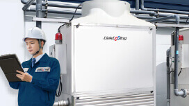
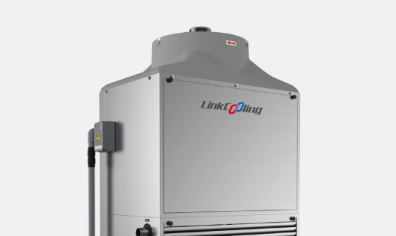
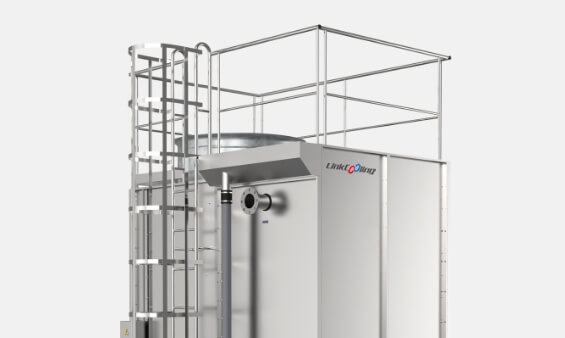
- Total Contamination Isolation: LinkCooling’s advanced Closed-Loop Combined Flow Cooling Towers are engineered to isolate your pristine internal process water completely from the outside atmosphere. Clean water or glycol loops remain sealed inside high-grade stainless steel or copper coils, ensuring that the fluid reaching your internal computer room air conditioning unit arrays or liquid cold plates is 100% particulate-free.
- The Combined Flow Advantage (Zero Scaling): Traditional counter-flow closed towers pull air upward against falling spray water, causing dry spots where minerals bake onto the hot metal tubes as rock-hard limescale. LinkCooling’s proprietary design uses concurrent downward airflow over the coils. This ensures that the heat-exchanger tubes remain 100% wetted at all times. Eliminating dry spots means zero scaling, preserving peak thermal performance for decades.
Phase 3: Multi-Circuit System Integration and Hybrid Designs
Modern data centers are frequently hybrid environments, requiring simultaneous support for legacy legacy racks and brand-new, hyper-dense AI rows.
- Dual-Circuit Segregation: LinkCooling builds multi-circuit towers capable of running two entirely independent fluid loops inside a single mechanical footprint. For example, Circuit A can deliver standard chilled water to perimeter crah units for traditional airflow containment rows, while Circuit B simultaneously manages an ultra-pure deionized (DI) water loop routed directly to localized Coolant Distribution Units (CDUs) for direct-to-chip liquid cooling or immersion cooling data center tanks.
- Footprint and Pumping Optimization: This consolidated engineering integration eliminates the need for separate, bulky equipment footprints outside the building. It drastically slashes your capital expenditure (CapEx) for piping networks and optimizes pump hydraulics, resulting in lower operational pumping costs and a highly optimized facility PUE.
Phase 4: Ensuring International Certification and After-Sales Service Coverage
Data centers operate on a 99.999% uptime mandate. Mechanical infrastructure must be fundamentally reliable and easy to maintain without disrupting live server operations.
- Certified Engineering Standards: Every cooling system engineered by LinkCooling is manufactured in strict compliance with leading international quality, safety, and performance standards. Our designs align with The Green Grid's metrics for Water Usage Effectiveness (WUE) and PUE minimization.
- Global After-Sales Service and Redundancy Architecture: We design our cooling infrastructure with N+1 and 2N component redundancy (including dual-drive fan configurations and automated internal valve bypasses). Backed by our comprehensive international technical support and rapid-response spare parts network, LinkCooling ensures that your data center stays cold, efficient, and online—no matter the processing load.
| Facility Engineering Target | Legacy System Vulnerability | The LinkCooling Engineering Solution |
|---|---|---|
| PUE Optimization (<1.2) | High energy consumption from constant mechanical compressor operation in traditional crac units. | High-efficiency closed-loop systems designed to maximize hours of compressor-free water-side economization. |
| Scale-Free Heat Transfer | Calcium carbonate scaling on coils decreases heat rejection efficiency over time. | Combined Flow Tower Geometry with concurrent downward airflow to maintain 100% wetted surfaces and eliminate scaling. |
| Particulate Defense | Airborne contaminants clog internal micro-channels inside liquid cooling data centers. | Complete closed-circuit fluid isolation, keeping external particulate-heavy sludge out of the internal CDU loops. |
| Footprint Minimization | Fragmented cooling systems require massive external real estate yards. | Multi-Circuit Towers that consolidate separate air-handling and direct-liquid loops into a single chassis. |
Build a Resilient Thermal Foundation with LinkCooling
Stop allowing legacy, inefficient cooling design to limit your data center’s computing capacity, increase your utility costs, or threaten your operational SLAs. Whether you are retrofitting an aging data hall packed with old computer room ac units or breaking ground on a multi-megawatt immersion cooling data center for AI deployment, LinkCooling has the field experience and technical capability to engineer the perfect system.
Let's design a cooling infrastructure that scales with your compute power.
Contact LinkCooling’s Engineering Team Today to consult with our data center thermal management experts and schedule your comprehensive facility thermal audit.