

2015-05-16
How to Calculate Heat Load and Select the Right Cooling Tower Size
When designing a cooling tower system, engineers must account for a range of site-specific environmental factors — including local wet-bulb temperature, circulating water flow rate, and the inlet and outlet water temperatures of the equipment being cooled. Together, these parameters define the cooling tower's design conditions.
From the customer's perspective, the core objective is straightforward: the cooling tower must handle the full heat rejection requirement of your equipment. To determine that requirement, start with the following fundamental formula (using water as the working fluid):
The Basic Heat Load Formula
Q = ( T₂ − T₁ ) × m
- T₁ — Inlet water temperature to the equipment (°C or °F)
- T₂ — Outlet water temperature from the equipment (°C or °F)
- m — Circulating water flow rate required by the equipment (L/hr)
- Q — Heat load generated by the equipment (kcal/h)
By applying this formula, you can calculate the heat dissipation demand for any piece of process equipment and use that figure as the basis for cooling tower selection.
Worked Example: Calculating Total Facility Heat Load
Consider a factory that needs to cool two types of equipment: a water-cooled chiller and an oil-temperature heat exchanger on a blow molding machine.
1. Water-Cooled Chiller
- Inlet water temperature (T₁): 33°C
- Outlet water temperature (T₂): 38°C
- Flow rate (m): 6,000 L/hr
- Heat load: Q = (38 − 33) × 6,000 = 30,000 kcal/h
2. Oil-Temperature Heat Exchanger (Blow Molding Machine)
- Inlet water temperature (T₁): 33°C
- Outlet water temperature (T₂): 36°C
- Flow rate (m): 6,000 L/hr
- Heat load: Q = (36 − 33) × 6,000 = 18,000 kcal/h
3. Total Facility Heat Load
30,000 + 18,000 = 48,000 kcal/h
This combined figure becomes the minimum cooling capacity required when selecting a cooling tower.
Three Ways to Select the Right Cooling Tower Size
Once you have determined your total heat load, there are three common approaches to identifying the right cooling tower specification:
-
Use a Cooling Tower Specification Chart
Match your calculated heat load against the manufacturer's rated capacity table to identify a suitable model. This approach works well when your operating environment closely matches the chart's standard design conditions (e.g., same wet-bulb temperature and flow rate assumptions). -
Provide Detailed Site Parameters to the Manufacturer (Recommended)
Supply the cooling tower supplier with your local wet-bulb temperature, required circulating flow rate, and the inlet and outlet water temperatures for each piece of equipment. This allows the manufacturer to perform a precise selection calculation tailored to your actual site conditions — the most accurate method available. -
Leverage the Equipment Manufacturer's Experience
In some cases, the original equipment manufacturer (OEM) can provide cooling tower sizing recommendations based on their experience with the same or similar machinery. This can serve as a useful reference, particularly when detailed site data is unavailable.
Many cooling tower manufacturers — including Linkcooling — maintain their own proprietary design tables that combine test data with real-world installation experience, enabling fast and reliable model selection without sacrificing accuracy.
Key Factors to Consider Before Finalizing Your Selection
Beyond raw heat load, two additional factors can significantly reduce effective cooling capacity in real-world operation and must be factored into your sizing decision:
Water quality and scale buildup: Limescale deposits on heat exchange surfaces act as thermal insulation, progressively reducing cooling efficiency over time. In open-circuit systems, this degradation can be substantial without regular treatment and maintenance.
Climatic variation: Wet-bulb temperature fluctuates with the seasons. A cooling tower sized for average conditions may underperform during hot, humid summer peaks — precisely when stable cooling is most critical for continuous production.
For both of these reasons, we recommend selecting a cooling tower with capacity slightly above your calculated requirement — typically by a safety margin of 10–20%. This buffer ensures stable, uninterrupted cooling performance across seasonal changes and accounts for the gradual effects of water quality on heat exchange efficiency.
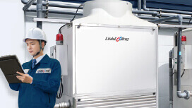
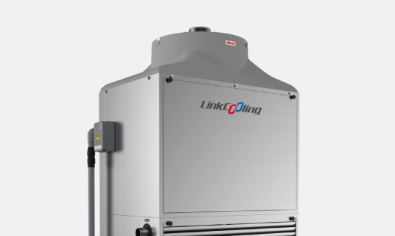
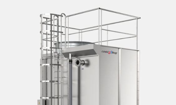
Closed-circuit cooling towers, such as the Linkcooling SCT and HCT-J series, inherently address the scale problem by physically isolating the internal process water from the external environment, eliminating the primary cause of efficiency degradation over time.
Get Expert Sizing Support from Linkcooling
With over 30 years of industrial cooling experience and a dedicated CTI-certified testing facility, Linkcooling provides precise cooling tower sizing calculations tailored to your specific equipment, flow rates, and site environment. Tell us your requirements and we will recommend the optimal model and configuration for your application.